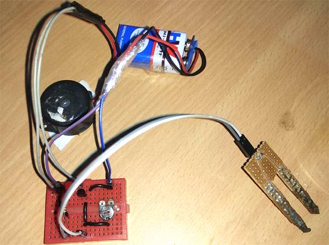
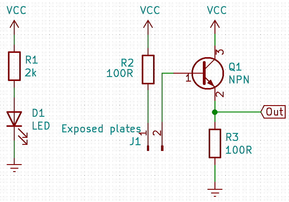
Using soil moisture sensor Circuit Diagram Soil Moisture Sensor Pinout. The Soil moisture sensor a.k.a the soil humidity sensor has four pins VCC, GND, Aout, Dout.These four pins can be used to get the soil moisture data from the sensor, The pinout of the Soil Moisture Sensor are as follows:. VCC is the power supply pin of the soil moisture sensor that can be connected to 3.3V or 5V of the supply. Circuit Diagram: Circuit Diagram of Soil Moisture Sensor Circuit is given below:. Working Explanation: This Soil Moisture Detector Circuit is very simple. Here we have used a soil moisture detector probe to sense the moisture in the soil and an NPN transistor to trigger the Buzzer and LED.This soil moisture detector probe is homemade and built using general purpose PCB (Perf board). The relay contacts switch OFF the motor pump. The pump remains OFF as long as the moisture sensor does not become dry again. The moisture sensor can be inserted deep into the soil whose moisture content needs to be sensed and controlled through the motor pump water. The pot R4 can be used to adjust the sensitivity of the moisture sensor element.
Feeding the sensor with an AC or a pulsating DC may fix this problem for a little, but we prefer to make a capacitor as a soil moisture sensor. There are some advantages to a capacitor. You avoid corrosion , but capacitive measuring also gives a better reading of the moisture content of the soil in comparison with the resistance measurement. 🌱 DIY Soil Moisture Sensor Circuit | Automatic Plant Watering System 🌱In this video, I'll show you how to make a Soil Moisture Sensor Circuit to automatica Assemble your soil moisture sensor circuit on a breadboard, as shown in the slideshow and described in Table 1. For advanced students, see the Help section for a circuit schematic and detailed description of how the circuit works. Click through the slideshow for step-by-step visual instructions.

Simple Soil Moisture Sensor Circuit Circuit Diagram
A Soil Moisture Sensor measures the water content in the soil by detecting changes in electrical resistance. Dry soil has high resistance, while moist soil has lower resistance, allowing the sensor to provide an analog or digital output representing the moisture level. This soil moisture sensor circuit uses a single transistor and 4 LEDs to indicate the soil moisture level. The transistor is used as a switch to light up the LEDs on the board. When there is enough water content, the transistor is turned off at pin 12, and current can flow through the sensor circuit and light up LEDs 6-9.