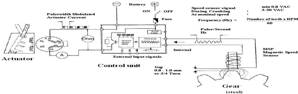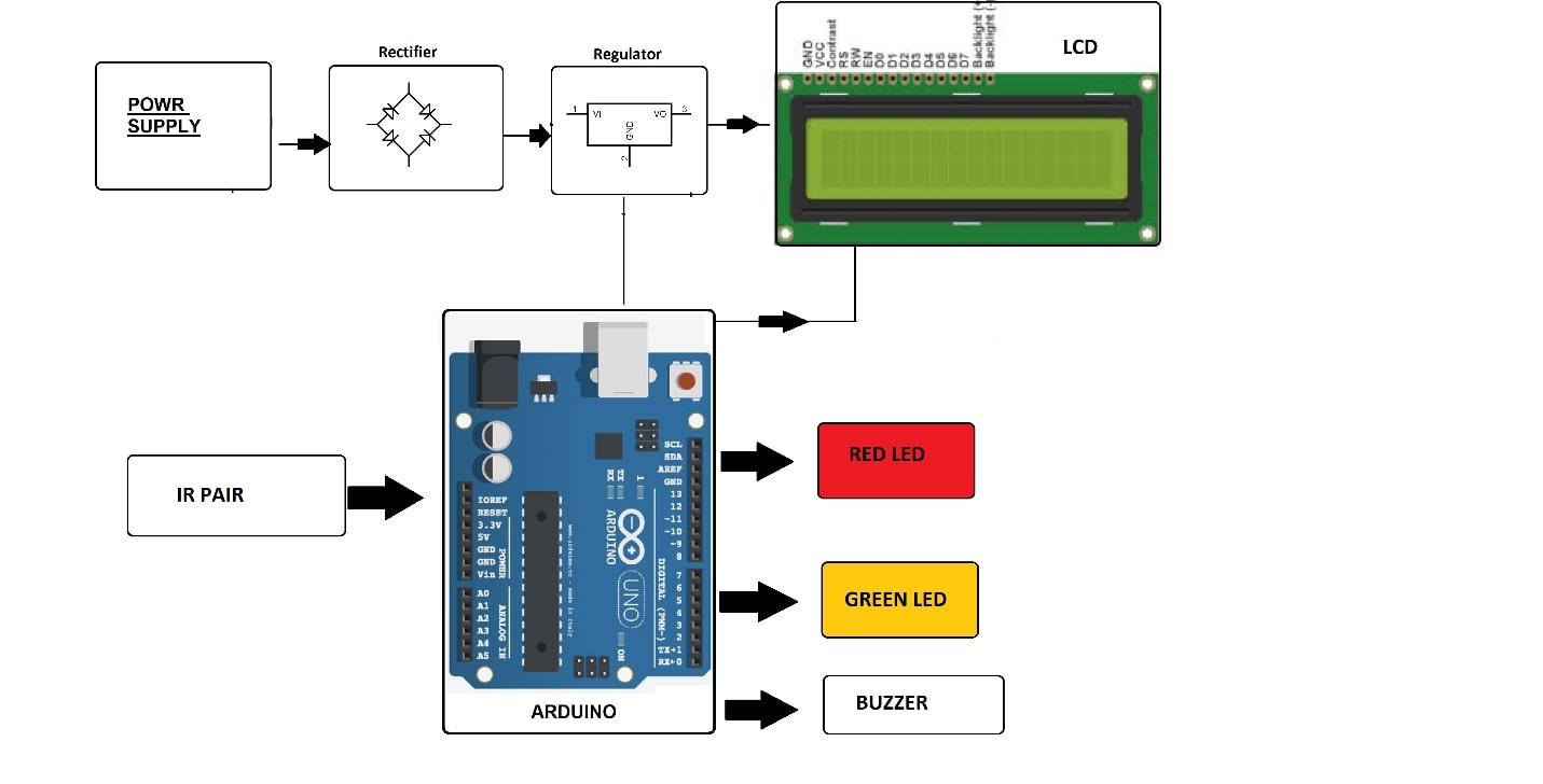
Figure 1 from Design and Development of Microcontroller Based Circuit Diagram The Badass Box will
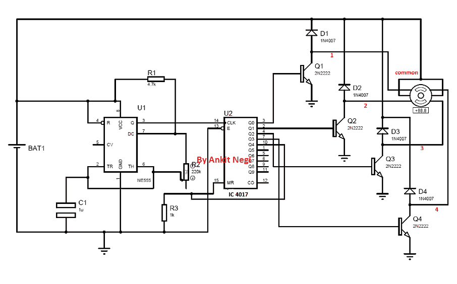
How to make Tone Generator using 555 timer Circuit Diagram Such periodic signals produce a
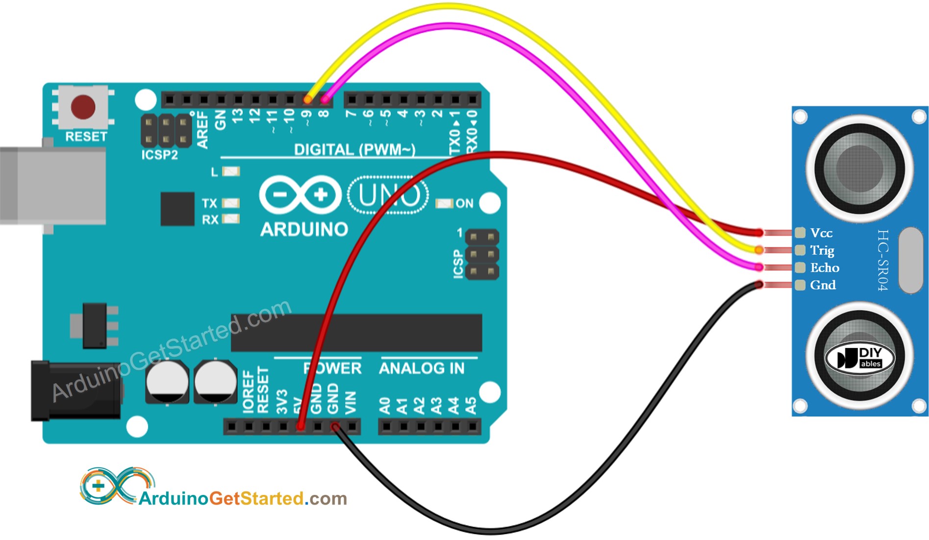
Arduino Ultrasonic Sensor Circuit Diagram The sensor has 4 pins. VCC and GND go to
Design of a Water Environment Monitoring Circuit Diagram 2.3. Capacitance Based Water Level Indicator 17
Motor Driver Circuit Diagram Learn how to use L298N Motor Driver Module for driving DC
Building a DIY Quadcopter a Complete Beginners Guide 25 Steps with Circuit Diagram Flight Controller
DIY Bluetooth Receiver for Any Amplifiers Under 3 8 Steps with Circuit Diagram Solder to
Gestures control based Home automation Circuit Diagram All the home automation systems are used to
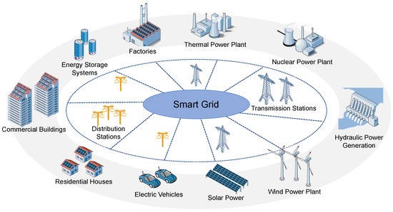
Control and Optimisation of Power Grids Circuit Diagram The real-time monitoring of the current and
Remote Control Circuits Page 8 Homemade Circuit Projects Circuit Diagram In this video, we are
Smart Road Safety and Vehicle Accident Prevention System for Mountain Circuit Diagram An IoT kit
How to Make an Awesome Fire Detector with Alarm Circuit Diagram Here Circuitsgallery comes with
Laser Distance Sensor Accuracy Continuous Measurement Circuit Diagram Basic Setup and Calibration of Laser Distance
How to build your own IoT device Circuit Diagram The on-chip transceiver integrates an RF
ESP32 Raspberry Pi Home Assistant Circuit Diagram All the results can be visualized in the
DIY Multifunction Energy Meter V20 12 Steps with Pictures Circuit Diagram In this cabinet I
What Materials Do You Need To Make A Simple Circuit at Ben Michael blog Circuit
Diy amplifier Basic electronic circuits Diy Circuit Diagram Learn how to use 3 transistors to
A Step by Step Ultimate Guide To Learn Arduino Circuit Diagram Essential Components of an
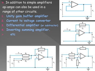
Presentation on Opamp by Sourabh kumar Circuit Diagram Figure 7 shows a voltage to current